ACI and Active-Active Firewall Cluster in Single-Pod and Multi-Pod Designs
Table of Contents
ACI Single Pod, Active-Active Firewall Cluster in Go-To Mode#
L4-7 Device Config#
A single Concrete Device, one or more Concrete Device Interfaces and one or more Cluster Interfaces, depending on the physical topology. See the document Service Graph Design Guide for ACI 5.2 and Later, page=55.
ACI Multi-Pod, Active-Active Firewall Cluster in Go-To Mode#
Stretched Active-Active Firewall Cluster in Go-To Mode, in ACI Multi-Pod Designs#
Designing cluster nodes in more than one data center is supported by ACI Multi-Pod. Each ACI pod has one or more firewalls in the active role. See the document ACI Multi-Pod and Service Node Integration, page=5.
Not every pod must contain a firewall cluster node. See the document ACI Multi-Pod and Service Node Integration, page=42.
aka Split Spanned EtherChannel mode which is a variation of Spanned EtherChannel mode.
Firewalls in each pod attach to service leaves using regular access policies.
Firewall-to-ACI using L3Out construct is not supported in this design.
The firewalls must support intra-cluster traffic redirection using the ICL Intra-Cluster Link; When traffic is received on one node, it can be redirected intra-cluster to the node that received the first leg of the communication, which is the node that has the connection state, whether it is on the same pod on on another pod. The connection state is hence synchronized between the cluster nodes.
–> there is no concern of having asymmetric North/South traffic patterns or asymmetric East/West traffic patterns.
Cisco does not support the design of a stretched routed active-active firewall cluster in ACI Multi-Pod and have vzAny the provider of a *(vzAny, ) contract between VRFs.
To minimize hair-pinning behavior of WAN-L3Out ingress traffic, leverage advertising host-routes in ACI, so that WAN-L3Out ingress traffic does not enter ACI on the wrong pod. Both two-arm and one-arm designs are supported.
Requirements for Stretched Active-Active Firewall Clusters in Go-To Mode in ACI Multi-Pod Designs#
- PBR and dedicated service BD(s)
- Anycast service feature.
[!caution] Using L3Outs to attach stretched active-active clusters to ACI is not supported.
Configuring the Anycast Service for the L4-7 Service Insertion in ACI#
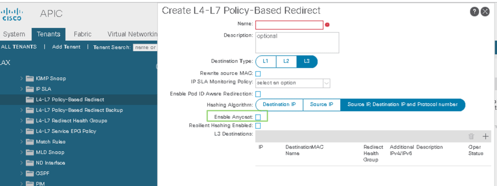
Anycast Service Configuration for L4-7 Service Insertion with PBR#
enable the flag Enable Anycast in the PBR policy.
ICL: Intra-Cluster Link#
Option 1#
ICL can be provided using a dedicated BD/EPG; The inter-pod link carries the ICL traffic between stretched firewall cluster nodes. TTL between multi-pod stretched cluster nodes must be <= 20ms for the ICL communication.
Option 2#
The firewalls may dedicate physical interfaces for ICL
Option 3#
The firewalls may use data plane interfaces (i.e. the same interfaces used for regular traffic) for ICL.
ACI Paths for the Firewall Cluster#
Firewall nodes of the same pod must be attached to the same vPC member switches. –> The same vPC Interface Policy Group attaches all cluster units of a pod. All cluster units attach to the ACI fabric using the same port channel on the firewalls’ side when they are configured with Firewall Spanned EtherChannel. See the document BRKDCN-2992, page=69.
[!Attention] Firewall Master and Slaves roles != Firewall Active and Standby roles.
L4-7 Device Config#
The L4-7 Device is composed of one Concrete Device per Pod, each Concrete Device representing the Cluster units of a same Pod.
Two firewalls total, one in each ACI Pod –> two Concrete Devices, on in each Pod: Cluster1 in Pod1 and Cluster2 in Pod2:
See the document ACI Service Graph Design Guide for ACI 5.2 and Later, page=56.
The MAC/IP addresses of the service cluster is learned on a leaf as a Local Learn anycast entry. The spines of the pod learn the anycast entry as a Local Learn and have also learned about it as Remote Learn entry (which is considered a backup path); A spine will systematically prefer the Local Learn entry over the backup Remote Learn entry. This is why a leaf prefers the locally-learned firewall cluster nodes when forwarding traffic.
See the document BRKDCN-2992_2024, pages=78, 70, 71, 77.
Designs with PBR#
for North-South traffic#
See the document ACI Multi-Pod and Service Node Integration, page=45.
for East-West traffic#
design with a single VRF#
See the document ACI Multi-Pod and Service Node Integration, page=51.
design with multiple VRF#
only two-arm design is supported. The inside and outside interfaces of the PBR nodes must attach to to (Provider, Consumer) pair VRF.
Independent Active-Active Firewall Cluster#
is not supported in ACI Multi-Pod.