Cisco ACI L4-7 Service Insertion: Standard Service Graphs with Firewall in Go-To Mode
Table of Contents
#QA SSG with L4-7 Device in Go-To mode: in which situations do we need only layer-2 BDs attached to the Device? Layer-3 BDs? one Layer-2 and one Layer-3 BD? what is the recommended design? Go-To mode == Routed mode When NAT needed on the L4-7 Device: use Service Graph in Go-To mode with NAT. another ‘sub-mode’ is an L3Out between the L4-7 Device and ACI. With both NAT sub-mode and L3Out sub-mode:
- the IP default gateway of the servers is on the ‘server-facing’ (typically known as ‘inside’) interface the L4-7 Device,
- one BD needs to be attached to the client-facing interface, one BD to the server-facing interface, #QA Isn’t there a Service Graph in Go-To mode with outside and inside L3 BDs? The table below summarizes the possible designs of a Standard Service Graph in Go-To mode.
| Standard Service Graph in Go-To mode design | Consumer-facing ‘outside’ interface | Provider-facing ‘inside’ interface | Comments |
|---|---|---|---|
| Service Graph in Go-To mode with outside L2 BD. Service Graph Design Guide for ACI 5.2 and Later.pdf#page=35 | is a layer-3 interface, attaches to a layer-2 BD (this is not part of an L3Out connection). An external routing device is also attached to the layer-2 BD (no L3Out) and is the IP default gateway of the firewall outside interface. Routing between the firewall outside interface and the external router is done across the L2 BD. (I do not need an L3Out because the external router is not exchanging routing with ACI but with another external device which is the firewall). The external router allows to steer from-WAN-ingressing traffic to the L4-7 Devices. | attaches to a layer-2 BD. The L4-7 Device is the IP default GW for the ‘Web’ EPG endpoints -> the L4-7 Device sits in the data path. The Provider-side BD flooding can be optimized. | NAT can be provided but is not mandatory design.> |
| Service Graph in Go-To mode with NAT [[Attachments/lib/Service Graph Design Guide for ACI 5.2 and Later.pdf#page=36]] | #verifyThis connects to the L3Out external BD | The L4-7 Device is the IP default gateway of the servers -> the L4-7 Device sits in the data path. The L4-7 Device provides NAT to internal endpoints.#verifyThis The IP default GW of the L4-7 Device is the L3Out external BD subnet | |
| Service Graph in Go-To mode with ‘inside’ L3Out | connects to an L3Out; | ||
| Service Graph in Go-To mode with VRF Sandwich [[Attachments/lib/Service Graph Design Guide for ACI 5.2 and Later.pdf#page=37]] | toward the WAN L3Out (not to be confused with the firewall L3Out that is also part of the design). The contract associated with the Service Graph Template is between the WAN L3Out EPG and the internal EPG. | The ‘inside’ L3Out attaches the L4-7 Device to the VRF where the Provider endpoints are. The Provider-side BD flooding can be optimized. | VRF Sandwich design is required to force traffic between (Provider, Consumer) pair to go through the L4-7 Device and not bypass it. |
Standard Service Graph with Firewall as Default Gateway#
The L4-7 Device must be the IP default gateway of the BD subnets of the (Provider, Consumer) pair in order to force their traffic to go to it by default. Therefore it must have an IP interface in each of those BD subnets, regardless of the topology (one- or two-arm).
DC East-West Communication#
(the example from the section Concrete Device Interfaces)
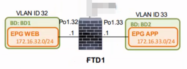
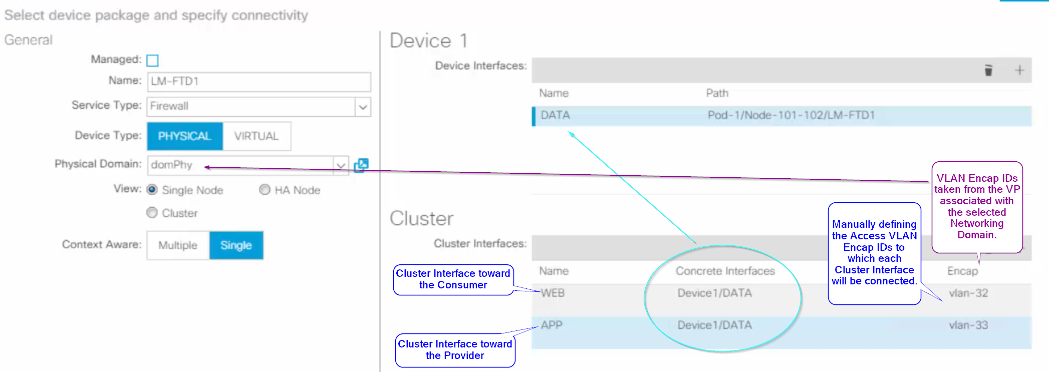
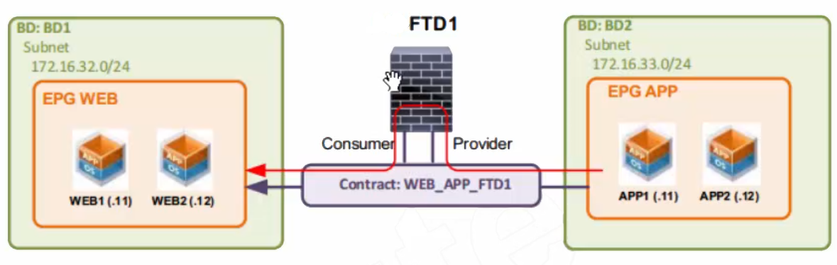
[!Caution] Migrating an app to Service Graph in Go-To mode with firewall as IP default gateway Make sure to remove Unicast Routing from the end user BDs afer applying the Service Graph Template. BD1 and BD2 must be re-configured with Unicast Routing turned off, since unicast IP routing will be carried by the LM-FTD1 firewall:
DC North-South Communication#
 I might use the same Concrete Device Interfaces for for East-West as well as North-South communication.
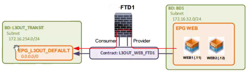
If one of the SGT Connectors is an L3Out EPG, then I need to use the concept of ==transit BD==. Otherwise, there is no BD to select for the L3InstP when applying the SGT.
The transit BD is a regular layer-3 BD that emulates a BD associated with the L3InstP.
I must create the transit BD before applying the SGT.
I might use the same Concrete Device Interfaces for for East-West as well as North-South communication.
If one of the SGT Connectors is an L3Out EPG, then I need to use the concept of ==transit BD==. Otherwise, there is no BD to select for the L3InstP when applying the SGT.
The transit BD is a regular layer-3 BD that emulates a BD associated with the L3InstP.
I must create the transit BD before applying the SGT.
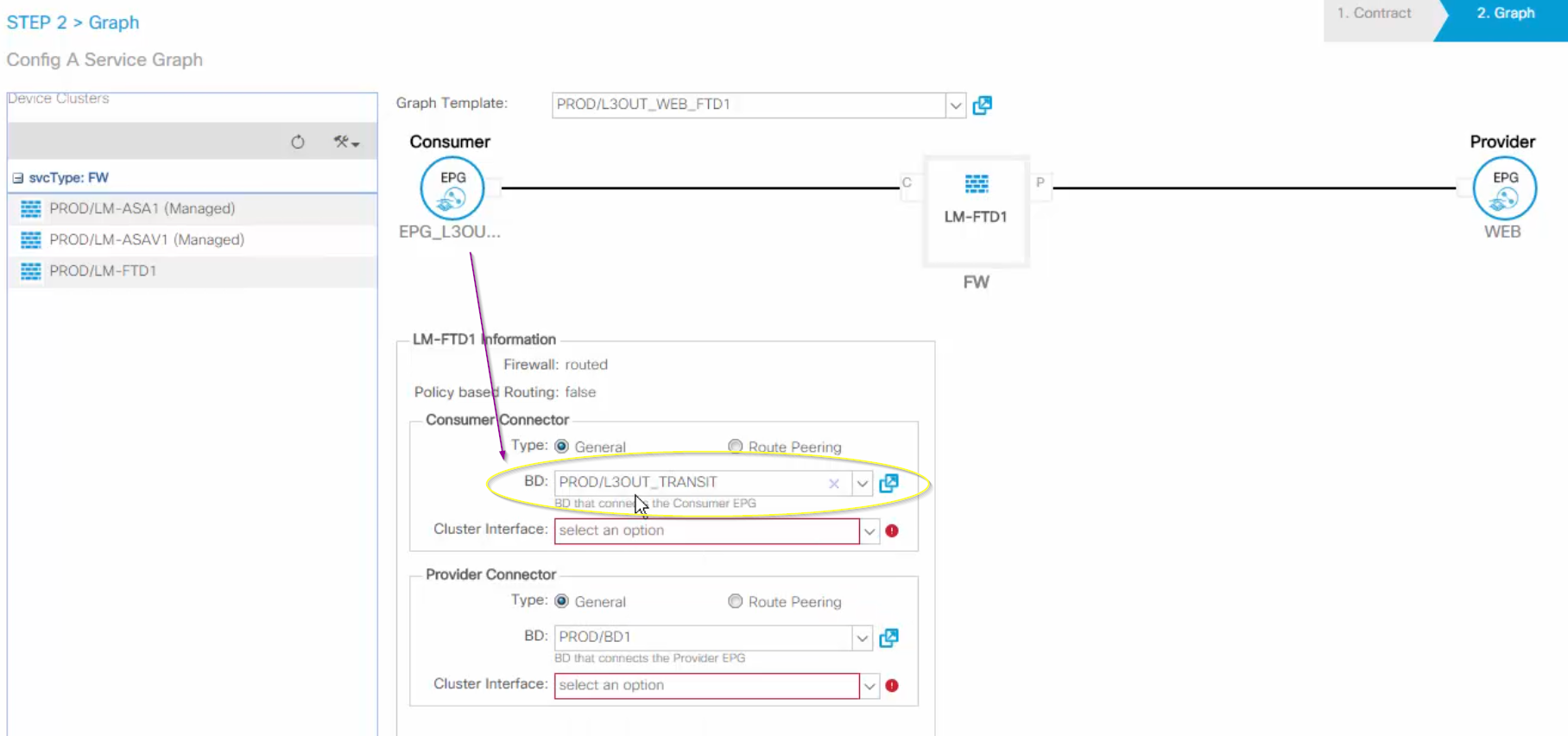
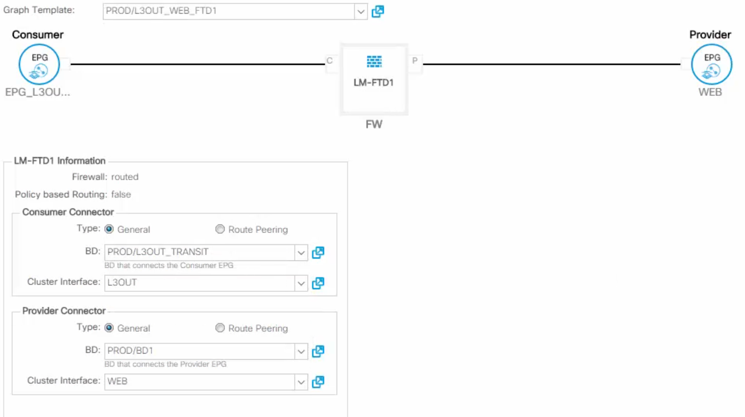 The L4-7 Device must have a route to involving the subnet IP addr of the transit BD ( #verifyThis a default route with next hop the BD SVI); So it must have an IP interface in the transit BD subnet.
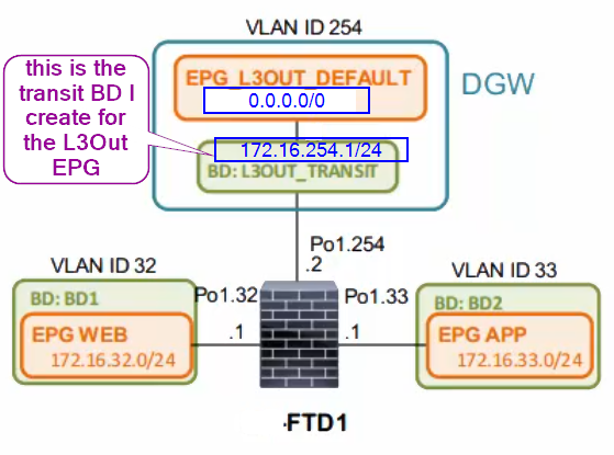
🥜 172.16.254.0/24 the IP subnet for the transit BD. LM-FTD1 has an IP interface 172.16.254.2 attached to the transit BD ‘L3OUT_TRANSIT’ ( #verifyThis I probably need to create an EPG for the transit BD and static path bind it for the firewall interface).
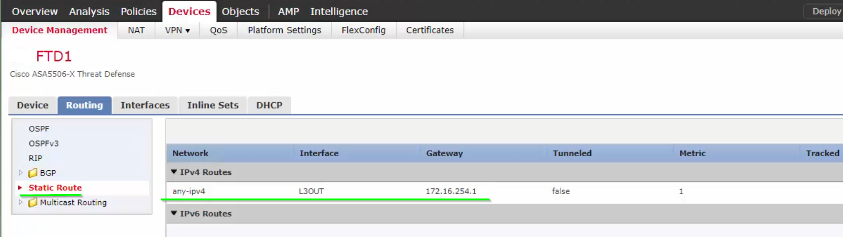
LM-FTD1 has the IP default gateway for EPG ‘WEB’.
‘EPG_L3OUT_DEFAULT’ is the L3Out EPG. ‘L3OUT_TRANSIT’ is a transit BD.
VLAN 254 is the encap ID used on the ‘L3OUT_TRANSIT’ BD. The firewall’s Po1.254 has VLAN encap 254 which must belong to the VLAN Pool/Networking Domain associated with the L4-7 Device in the first place.
 #QA Routing from the transit BD subnet to the L3Out subnet is done by ACI since both belong to the same VRF? Why do I need it in the first place?
Standard Service Graph with Firewall not as Default Gateway + with L3Out#
see [[#Method 2 no NAT but VRF Sandwich and L3Out]] see [[Firewalls]] Since this is a Service Graph, we need a manual contract only between the end user EPG and the ‘WAN Edge’ ext.EPG. ACI will create Shadow Contracts and Shadow EPGs automatically.