Inserting firewall packet inspection services in Cisco ACI data paths without offloading the gateway service off the fabric
Table of Contents
PBR in two-arm design, the PBR Node Interfaces are in the same VRF#
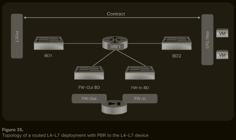
#QA In the SGR in Go-To in Two-arm design, how does IP routing on the firewall scale when we have dozens of (Provider, Consumer) pairs? #QA How cumbersome is the management of the static IP routes related to the SGR on the service device? #QA Is BD2 the IP default gateway for EPG Web endpoints? #QA Which component takes the role of IP default gateway of the firewall: BD1 or FW-Out BD?
Requirements#
The Service Devices are configured in Go-To mode. The Service Device must attach to layer-3 BDs, whether Service BDs or User BDs.
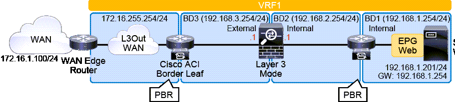 the L4-7 Device might not have an IP interface in each BD subnet of the (Provider, Consumer) pair.
L3Out connects the WAN router to ACI. It does not relate to the firewall.
the L4-7 Device might not have an IP interface in each BD subnet of the (Provider, Consumer) pair.
L3Out connects the WAN router to ACI. It does not relate to the firewall.
[!NOTE] SGR and BD Whether with Two-Arm or One-Arm, the SGR must connect to only layer-3 BDs. If one of the attached BDs is layer-2, the topology is not supported by Cisco.
SGR and L3Out EPGs#
SGR might attach to L3Out EPGs; There are limitations to consider. PBR being applied to customer side only is enough. On the provider side, the provider EPG traffic will invitably reach the firewall because there is no other way to bypass the L3Out when trying to reach the consumer. ( #QA is BD1 network advertised only through the L3Out?) See the document ACI Service Graph with PBR Design White Paper, page=14.
SGR might have both Connectors in L3Out: #QA Are PBR node interfaces in the same VRF? If so, when do I need such a design? See the document ACI Service Graph with PBR Design White Paper, page=14.
PBR Node Interfaces are in different VRFs#
The PBR node has an interface in the provider VRF and the other in the consumer VRF.
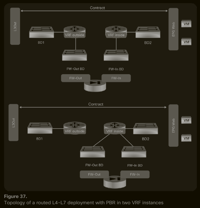
#QA any sample use cases?
PBR Node Interfaces are on either the Provider or Consumer VRF#
The PBR node can also have both interfaces in the same VRF, either the provider or the consumer VRF, but never on a third VRF.
According to a Cisco Live session, most of Cisco’s customers use L4-7 service integration with PBR in Routed Mode and one-arm deployment topology.
The L4-7 Service Graph Template Connectors can be placed in the same BDs as the (Provider, Consumer) pair. We need neither L3Out to the L4-7 Device nor NAT on it. When the L4-7 Device is not attached with L3Out to ACI but rather with regular BDs, then it is considered as part of the fabric.
PBR Node in One-Arm Design#
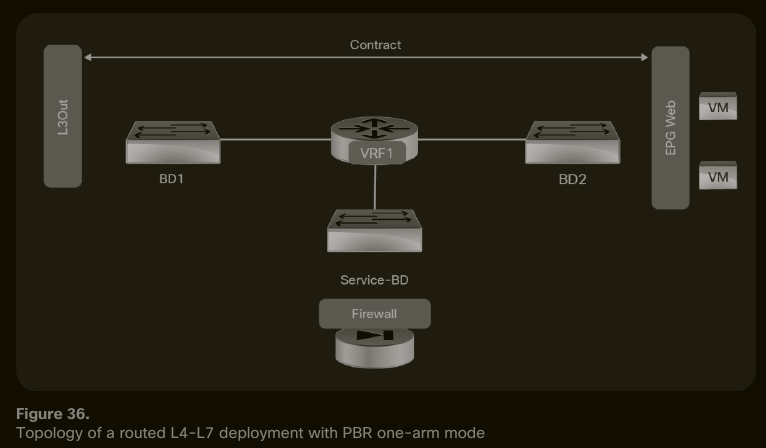
It is the only design that supports VzAny to VzAny Contracts with PBR enabled.
Requirements#
The Service Devices are configured in Go-To mode. The BD to which the Service Device attaches must be a layer-3 BD:
- if it is a Service BD:
- the Service BD has its own IP subnet and the L4-7 Device has an IP interface in it.
- #verifyThis The Service BD has one or more IP routes with next hop the Service BD’s SVI.
- if it is one of the (Provider, Consumer) BD:
- the Service Device has an IP interface in the user BD,
- The Service BD has one or more IP routes with next hop the user BD’s SVI. #QA how to achieve this?
PBR Node has the internal interface attached to an L3Out#
This is not an L3Out that connects an external router; It is an L3Out that connects to the intern-facing firewall interface. North-South traffic will traverse the firewall as part of IP routing semantics and will be subject to firewall traffic inspection. East-West traffic involves the PBR through the L3Out.