Firewall Manual Stitching in ACI
Table of Contents
aka Network Stitching. This is the manual method to insert L4-7 services; VLANs, EPGs and bridge domains are manually created, and EPGs are manually assigned to the L4-7 device interfaces, statically with Static Path Binding or dynamically with a VMM domain. If we have to insert more than one L4-7 device, repeat the above process as much as there are devices to integrate.
L4-7 device vs L4-7 Device#
An L4-7 device in the manual stitching context is one firewall, one ADC, etc. A L4-7 Device in Service Graphs is the Logical Device, which might contain one or more Concrete Devices.
🍌 Manual stitching of an ADC: Inserting ADC services using manual stitching involves EPG extension and/or L3Out, BDs and contracts to connect the ADC interfaces (client-facing interfaces and server-facing interfaces) to ACI.
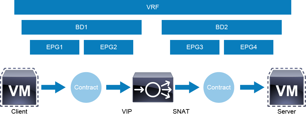
🍎 Manual stitching of 2+ L4-7 devices:
See ‘Service Graph Design Guide for ACI 5.2 and Later’ document on cisco.com.
In the document, Bridge Domain 1 is NOT an external BD. It looks like it is attached to the Outside router but it is really not; It is attached to the border leaf, and the border leaf is attached to the outside router.
🍍 Manual stitching of a firewall: This is the case where the firewall is acting as an IP default gateway for ACI BD subnets; Each BD is associated with an EPG. The EPG is extended to the leaf interface(s) where the firewall is connected (called Service Leaves). So the firewall has its interface attached to the user EPG’s BD.
Requirements#
Deploy the L4-7 Devices (firewalls, load balancers, etc.) physically in the data path of the (Provider, Consumer) pair. VLANs and VRFs are typically required.
Pros#
Traffic is unavoidably steered to traverse the L4-7 devices.
Cons#
The service node must be inserted in the data path between the (Provider, Consumer) pair to steer the traffic to the service node. Troubleshooting or decommissioning applications involve some degree of complexity.