How to Steer Traffic to a Firewall Using ACI L4-7 Service Insertion
Table of Contents
If I configure the IP default gateways of the (Provider, Consumer) pair on ACI and attach an L4-7 Device to ACI, IP routing traffic involving the (Provider, Consumer) pair will bypass the Service Device due to routing in ACI itself. To circumvent that, there are three known methods to force traffic toward the L4-7 Device.
Method 1: NAT on the L4-7 Device#
Method 2: SGR (no NAT on the L4-7 Device)#
Method 3: VRF Sandwich and L3Outs#
No NAT on the L4-7 Device.
North/South Traffic use case#
See ACI Service Graph with PBR Design White Paper 2024, page 4
A note on VRF Sandwich#
The Service Device is in Go-To mode. Both of its interfaces (Inside and Outside) attach to ACI using L3Outs, #PersoNote because it is considered not part of the ACI fabric.
This is called ==VRF sandwich design== because the L4-7 Device sits in the middle of two VRFs, like a sandwich.
The firewall is also called a VRF front-ending firewall.
ACI is configured as layer 3, i.e. the IP default gateways for the internal EPGs are ACI BDs. I must put the firewall’s Inside interface on the same VRF as the internal networks. I must set the firewall’s Outside Interface on the same VRF as the WAN routers. Typically SVI are used as layer-3 interface types for the L3Out with firewalls. I must set IP routing on the ACI border leaf, which is attached to the internal networks, in a way that it forwards all traffic to the firewall’s internal interface (192.168.2.1). I must set IP routing on the ACI border leaf, which is attached to the external networks, in a way that it forwards from-WAN-ingressing traffic to the firewall’s external interface (192.168.3.1) if it wants to reach a particular internal subnet. To reach the L3Out EPG, traffic from ‘Web’ BD subnet goes to the border leaf attached to L3Out ASA-in, which forces the traffic to traverse the service node by means of the default static route. Also, a from-the-WAN ingressing traffic, that reaches the WAN border leaf, is forced to traverse the service node because the WAN border leaf is configured with a static route that points to the service node ( #PersoNote could be a static default route if there is only one internal subnet that needs to be reachable from the outside). The diagram can be also drawn in the following manner:
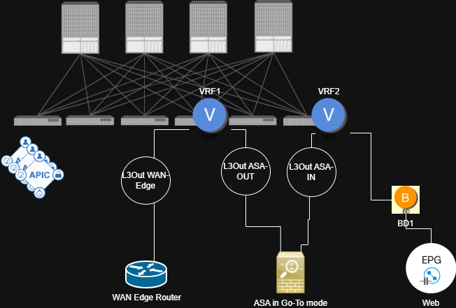
DC North-South traffic is inspected by the firewall as per this design.
Another way to steer traffic to the service nodes is by using PBR.
To let DC east-west traffic be inspected by the same firewall too, we need a similar VRF sandwich design but with PBR ( #QA can this not be achieved without VRF Sandwich?), which is another design option.
This design method can be included in:
- ACI single-pod or Multi-Pod design,
- manual insertion of L4-7 service nodes,
- Standard service graphs,
- Service graph redirects. This design method is valid:
- for north-south traffic (like illustrated in the top)
East/West Traffic Use Case#
The L3Out WAN is replaced with a regular L3 BD of another EPG: See ‘ACI Multi-Pod and Service Node Integration’ document from Cisco, page 28.
The rest of the configuration is the same as in the north/south use case.