ACI L4-7 Service Insertion: Service Graph with PBR
Table of Contents
[!TLDR] Personal Observation I find few sources discussing standard SG and more literature discussing SGR. It seems to me that Cisco is pushing toward SG with PBR whenever a design involves L4-7 Service Devices.
aka Service Graph with Policy-Based Redirect, Service Graph Redirect. I call it SGR. One-Node SGR: Service Graph with one PBR Node.
Concept of a multi-node Service Graph#
the concept of node in the terms ‘single-node SG’ or ‘multi-node SG’ refers to the L4-7 Devices in the SG. So, the term ‘multi-node Service Graph’ refers to a Service Graph with multiple L4-7 Devices, where each L4-7 Device could be:
- composed of a single Concrete Device, which refers to a single device (a firewall, an IPS, a load balancer) or to an Active-Active cluster,
- composed of $2^+$ Concrete Devices like an Active-Standby firewall cluster So:
- a Service Graph with a single Active-Active firewall Cluster or Active-Passive firewall cluster is considered a single-node Service Graph
- a Service Graph with $2^+$ independent firewall clusters is considered a multi-node Service Graph
- a Service Graph with $2^+$ independent L4-7 Devices is considered a multi-node Service Graph corollary: Two-Node SGR is a SGR with two L4-7 Devices. Not to be confused with Policy-Based Routing. Cisco assumes that I insert a stateful Services Device in the SGR. If the Device does not perform IP addr translation, I should activate PBR in both directions of the (Provider, Consumer) pair. #QA SGR with PBR might/should be applied only to one side of the (Provider, Consumer) relationship. Technically supported: intra-EPG Contract mit PBR, intra L3Out EPG Contract mit PBR ( #QA what for?) PBR leverages the full layer-2 and layer-3 capability of ACI.
[!Caution] IP Routing vs PBR When dealing with PBR, I need to remain alert to the fact that the existence of IP routes to/from the (Provider, Consumer) pair can be misleading and does not mean the traffic is forwarded directly between them; I need to always find out where the traffic redirection policy is enforced and that’s where the traffic is redirected to.
Advantage of Service Graphs with PBR over Standard Service Graphs#
Limited scalability of Standard Service Graphs: Remember, when using SG, the L4-7 must be in the data path between the (Provider, Consumer) pair :luc_arrow_big_right: A dozen (Povider, Consumer) pairs that require security policies imply inserting the Service Graph in the data path and modifying the placement of IP default gateways :luc_arrow_big_right: requires ACI config change. A scalable L4-7 Device design with less impact on the DC network topology involves Service Graph with PBR. This technology leverages the benefit of Service Graphs (i.e. fewer contracts for the same output) with the advantage of physically placing the L4-7 Device anywhere in the DC network. With ACI 5.2+ and SGR, the Service Device does not need to attach to ACI using L3Outs for the traffic to be forced to the Service Device; The Service Device is considered part of the ACI fabric because it may attach to ACI using simple Layer-3 BDs.
PBR Destination#
aka PBR Node(s): The L4-7 Device that performs the PBR feature.
PBR Contract#
a contract where a subject contains reference to a Service Graph Redirect.
vzAny PBR Contract#
A PBR Contract that involves vzAny as Provider or Consumer.
PBR Node Bridge Domain#
is a BD to which the PBR node has an interface attached to. If the BD connects only PBR Node interfaces, then it is a Service BD.
Multinode PBR#
characteristic of a SGR composed of 2+ PBR nodes. Attention: multi-node PBR != multi-node SG The document ACI Service Graph with PBR Design White Paper, page=13, describes multi-node SGs but not multi-node PBRs.
Bidirectional PBR#
PBR is applied to the contract-matched traffic in both directions of the contract (i.e. from Consumer to Provider and from Provider to Consumer).
unidirectional PBR#
PBR is applied to the contract-matched traffic only in one direction.
PBR requirements#
- ACI must be a layer-3 fabric, i.e. ACI holds the IP default gateways for the (Provider, Consumer) pair and the Service Devices.
- VRF in enforced mode (which is the default mode).
- Like Standard Service Graphs, a Service Graph with PBR requires the existence of a ACI contract between a (Provider, Consumer) pair of EPGs/ESGs and leverages Service Graph Templates.
Powerful PBR Use Cases#
See the document BRKDCN-3982, page=7 and 8.
Number of Concrete Devices and Logical Devices required#
See the document BRKDCN-2992, page=60.
Which Traffic to Apply PBR to#
When it comes to applying SGR to a (Provider, Consumer) pair, it might be in unidirectional (traffic from Provider to Consumer or from Consumer to Provider) or bidirectional (Provider to Consumer and Consumer to Provider traffic). Do not create a Service Graph Contract which redirects all traffic between a (Provider, Consumer) pair because ARP traffic might match the filter and get wrongly redirected to the L4-7 Device; This negatively impacts ARP packet flow; Redirect for example all IP traffic or selective traffic flows.
PBR associated with a Contract that is applied to (VzAny, VzAny) pair#
Associating SGR with a (VzAny, VzAny) Contract:
- do not use the ACI default filter of the tenant common. Apply PBR on matched IP-based traffic only.
- requires PBR in One-Arm design. #QA What about the Contract’s Subject Filter order?
Where is PBR applied?#
PBR is applied on the leaves hosting the (Provider, Consumer) pair. I can verify whether PBR is applied or not with the ACI command show service redir info.
How PBR is applied when associated with a contract#
I create a Contract. I create a Subject. I associate a standard service graph or a Service Graph Redirect with the Contract at the Subject level. The filter that make the Subject must have the Permit action; It acts as a matching criteria for SSG in general and for SGR in particular. i.e. a filter with Deny action for a Subject that has PBR on makes no sense because it will drop the traffic.
Selective Redirection of Traffic#
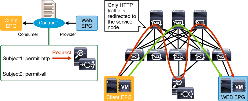
I can select some traffic to be redirected to the Service Device and the rest to go directly between the (Provider, Consumer) EPG pair using Contract Subjects:
- Subject1 is associated with a SGR and has a Filter that matches HTTP traffic with action == Permit. Subject2 is not associated to an SGR but has a Filter that matches IP traffic with action == Permit. Traffic matching Subject1/Filter1 will be redirected to the Service Node. Traffic matching Subject2/Filter2 will directly flow between the (Provider, Consumer) pair:
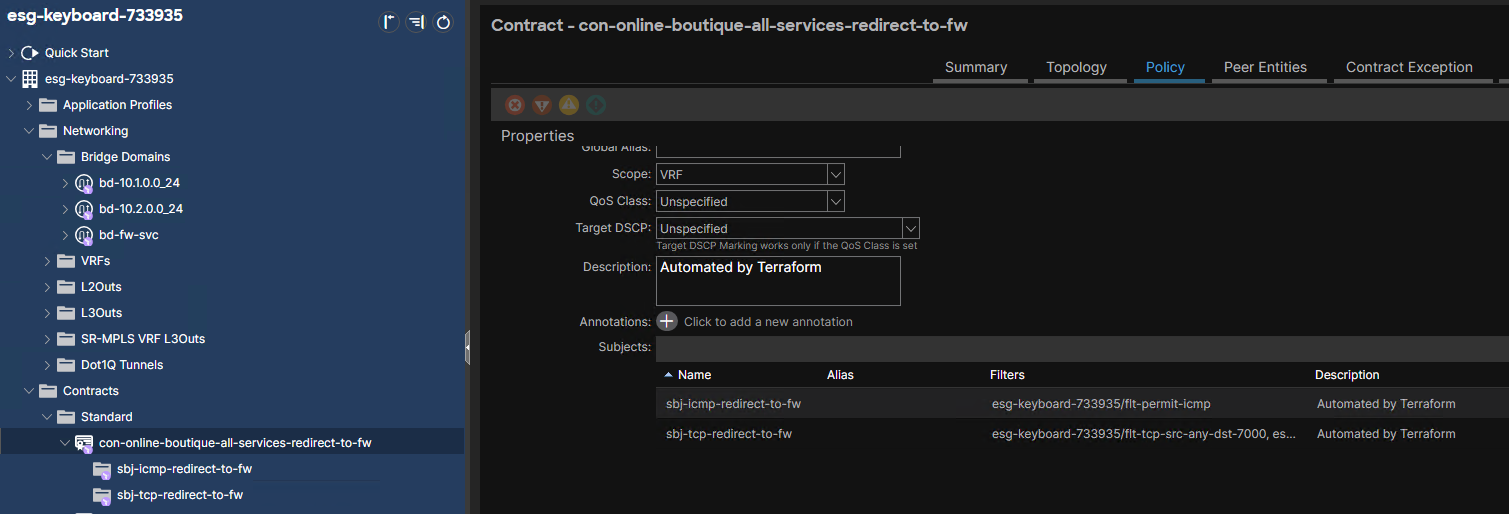
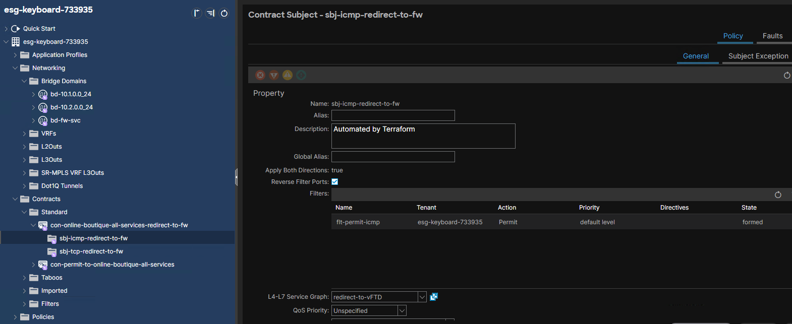
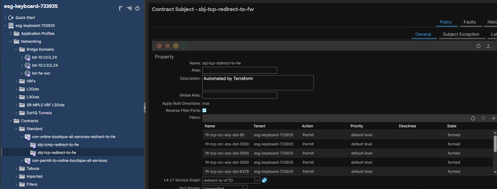
- This Contract has two Subjects. Both involve a Service Graph. But the Subject has no conscious as to whether it is a SSG or SGR.
PBR Policy aka Policy-based Redirect policy#
aka Redirect Policy in the menu where SGT is applied:
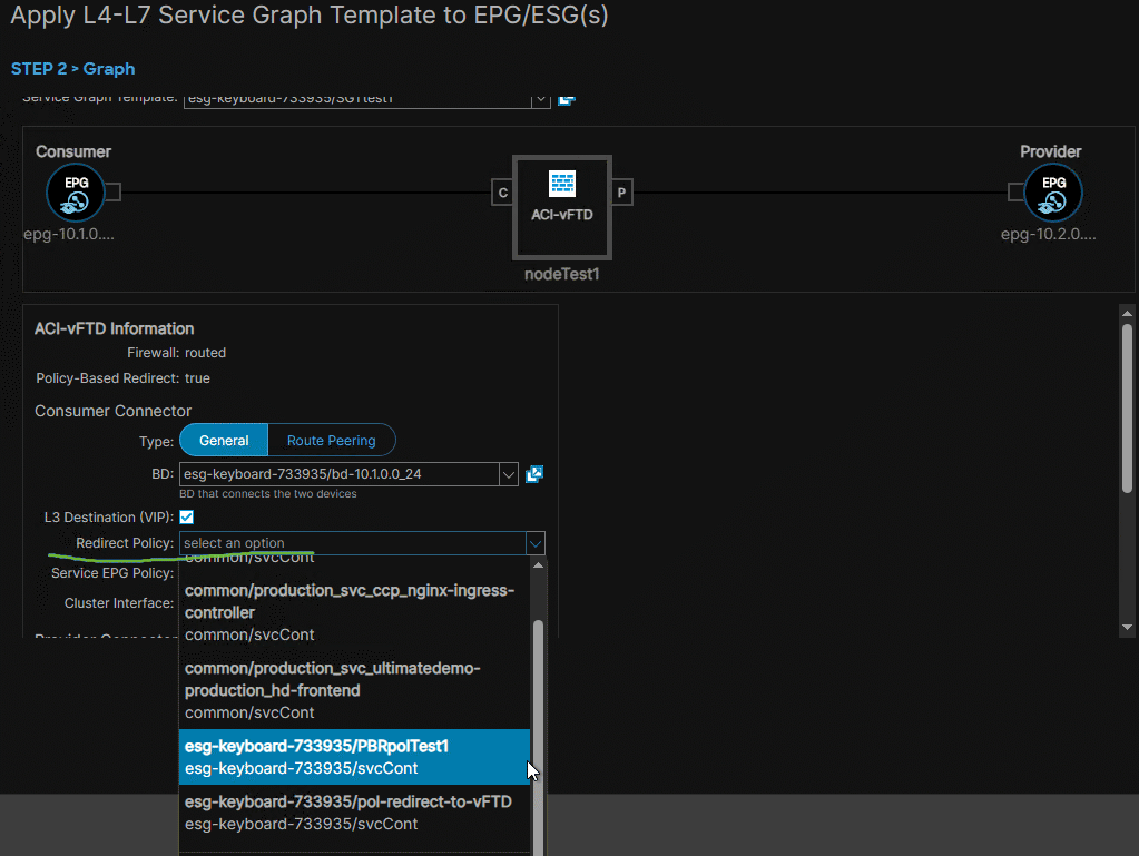 This is the policy required for the SGT to re-route traffic toward the L4-7 services device.
As the name suggests, this is required only for SGR.
defines MAC and IP addresses of the active firewall or load balancer as seen by ACI.
I must create a PBR policy:
This is the policy required for the SGT to re-route traffic toward the L4-7 services device.
As the name suggests, this is required only for SGR.
defines MAC and IP addresses of the active firewall or load balancer as seen by ACI.
I must create a PBR policy:
- regardless of the SGR working mode,
- one, if my L4-7 Device has One-Arm design (see the section on the L4-7 Device is in One-Arm design),
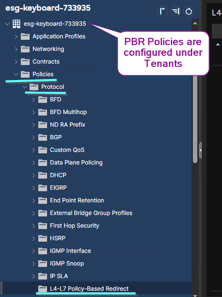
- two, if Two-Arm design (see the section L4-7 Device is in Two-Arm design). Provider side / Consumer side have no impact on the number and type of PBR policies to be created. In a single ACI fabric design, the leaf where the PBR policy is applied == the location where the policy is enforced (remember the table for ingress and egress enforcement from the Contracts Design Guide). This is not true with ACI Multi-Site designs like ACI Multi-Site and Active-Standby Firewall Clusters with Service Graph Redirect designs.
[!Attention] The importance of the Policy enforcement location table in the document ‘ACI Contract Guide’, page=20 lies in finding out - in the case of PBR - the leaf where the traffic between the (Provider Consumer) pair gets redirected, which trumps the IP routing semantics.
See the document ‘ACI Contract Guide, page=21.
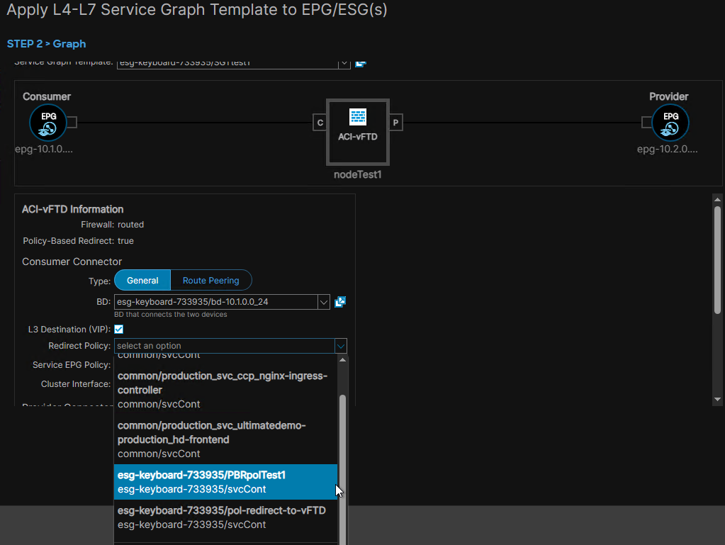
 PBR Policy != Device Selection Policies or Logical Device Context.
The PBR policy is required at the time of Applying the Service Graph Template:
PBR Policy != Device Selection Policies or Logical Device Context.
The PBR policy is required at the time of Applying the Service Graph Template:
Direction of the PBR Policy#
can be applied at the Provider side and/or the Consumer side of the SGT.
When the PBR policy is applied for both the Provider and Consumer sides, it is said to be ‘applied in both directions’.
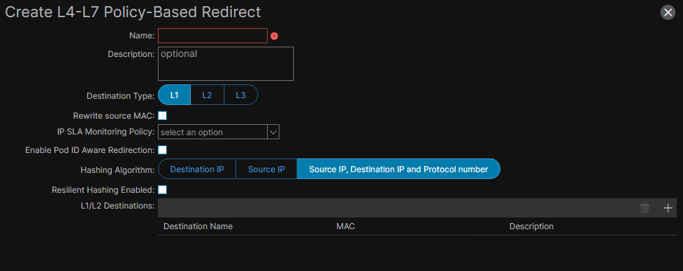
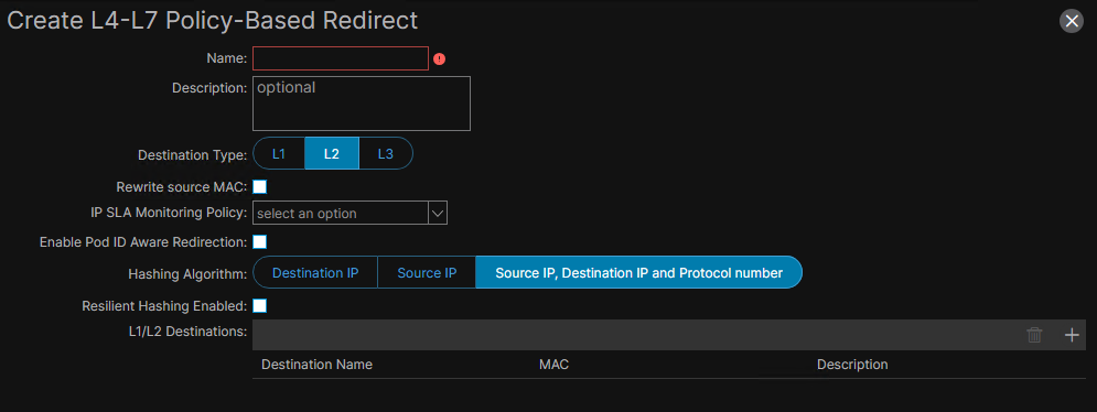
PBR Destination is L1 or L2#
#lab I must fill in the MAC address of the L4-7 Device under L1/L2 Destinations:
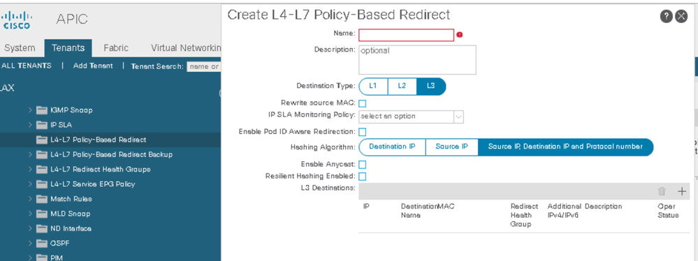
PBR Destination is L3#
I must fill in the MAC and IP addresses of the L4-7 Device under L3 Destinations:
L4-7 Device is in Two-Arm design#
Example: Two PBR policies total, one for the firewall internal interface and one for the firewall external interface. Both PBR policies contain the same IP and MAC addresses. See the document ‘ACI Service Graph with PBR Design White Paper’, page=92.
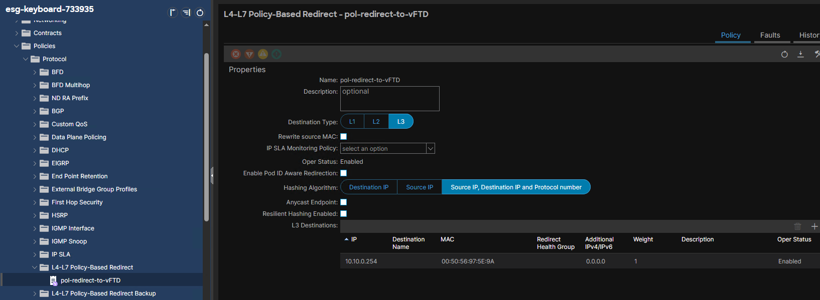
L4-7 Device is in One-Arm design#
Example: One PBR policy where I define a single IP address and a single MAC addr. For Active/Standby HA firewall clusters, I insert the virtual IP and the virtual MAC addresses. #labbed
Symmetric PBR#
is a feature of the L4-7 Policy Based Redirect policy. Symmetric PBR is not a radio button or a check button.
purpose?#
ensures that both communication legs of a same traffic flow (i.e. ingress and egress traffic flow) traverse the same Service Node which holds the connection state.
when required?#
When I have multiple independent active firewalls or multiple independent Active-Active firewall clusters that are involved in the SGR, and there is no mechanism to synchronize the connection state table between them.
configured for any PBR policies?#
no; Only when the L4-7 Policy Based Redirect policy contains 2+ PBR destinations.
[!NOTES] I configure a PBR policy with $2^+$ MAC/IP entries when I have multiple independent active Service Nodes involved in the SGR (eg. the ACI Site contains two or more independent firewalls or two or more active-active firewall clusters).
There is no talk on symmetric PBR if there is only a single firewall in the DC network design.
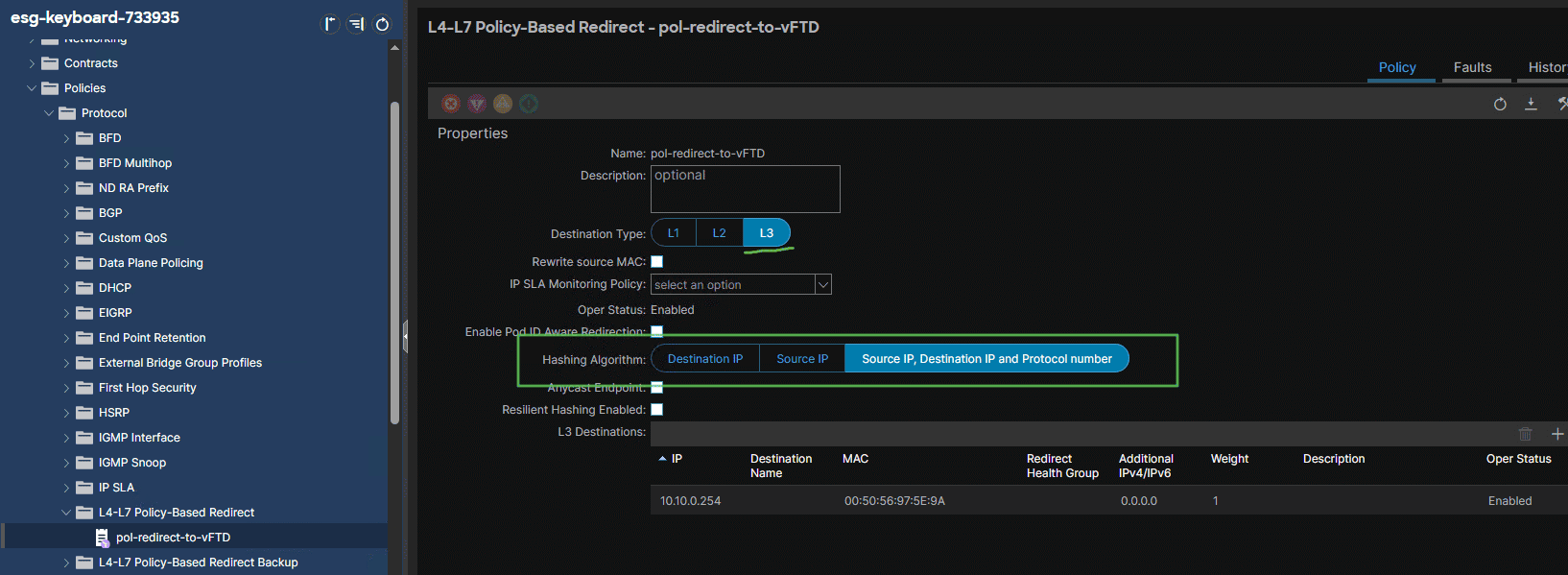
Hashing function#
is part of the Symmetric PBR mechanism.
achieves load balancing of traffic across all available active firewalls that are part of the L4-7 Policy Based Redirect policy. This is achieved regardless of whether they are part of the same cluster (like in a active-active HA cluster) or of different clusters (e.g. in a design with multiple independent active-passive HA clusters).
Three algorithms are available for load balancing when the service node is in routed mode:
Destination Group#
#verifyThis In the case of Routed mode SGR, a destination group is the group of PBR nodes, identified with a MAC and IP address, that are defined under the PBR policy and which serve the redirection of traffic in a zoning rule. See the document ‘ACI Service Graph with PBR Design White Paper’, page=113. #QA Can more than one Destination Group exist for a L4-7 Device? Example 1: Two destination groups when the SGR is bidirectional and L4-7 Device is in two-arm design. #QA why? (see the document ‘ACI Contract Guide White Paper’, page=109-110):
- Rules 4225 and 4248 show two Destination Groups (4 and 5), which correspond to the Provider-side and the Consumer-side interfaces respectively.
- Rules 4229 and 4254 are there to ensure the return traffic from the Service Node back to the fabric. Example 2: One destination group and L4-7 is in one-arm design (see the document ‘ACI Contract Guide White Paper’, page=188-189):
- Rules 4226 and 4261 show a single Destination Group (3) which corresponds to the one-arm design.
- Rules 4249 and 4258 are there to ensure the return traffic from the PBR Nodes back to the fabric.
Summary Table#
| ACI Design | FIrewall HA or Clustering Design | Firewall operational mode | Number of required PBR policies | number of MAC and IP addresses per PBR policy |
|---|---|---|---|---|
| single Site | one HA firewall | Go-To mode | 1 | 1 |
| single SIte | two independent HA firewalls | Go-To mode | 1 | 2 |
| single Site | one firewall cluster | Go-To mode | 1 | 1 |
| single Site | one firewall cluster with $3^+$ nodes | Go-To mode | 1 | 1 |
| single Site | two independent firewall clusters | Go-To mode | 1 | 2 |
| Multi-Site | one independent HA firewall per Site | Go-To mode | 2 | 1 |
| Multi-Site | one independent firewall cluster per Site | Go-To mode | #TBC | #TBC |
Creating a SGR#
Create the necessary ACI access policies
Create the PBR Policy
Create the L4-7 Device
Create the SGT
Apply the SGT
Verify the Contract’s Subject associated with the SGT.
Verify the Logical Device Context / Device Selection Policy.
Other#
#QA SGR in Go-Through mode and the use of End User BD?