Posts for: #Microlab

Junos Generated Routes

Topology

graph LR
net1(LAN1_172.17.99.0/24) 
net1 <--> R1
R1 <--> |WAN1_10.10.10.8/30|R4

Configuration and Interpretations

Desired outcome: I want to configure a generated route on R1 for the prefix 172.17.99.0. Currently, the prefix 172.17.99.0/24 is directly attached to ge-0/0/6. I want to make R1 advertise the generated route 172.17.96.0/19 toward its BGP neighbor R4 only when R1 receives the BGP route 10.22.1.0/26 from R4 (which is configured as an aggregate route on R4) and successfully imports it from BGP into inet.0. On R1, at the moment there is only one contributing route for the generated route, which is 17.17.99.0/24.

[Read]

Junos Aggregate Routes

Topology

graph LR
net1(LAN1_172.17.99.0/24) 
net1 <--> R1
R1 <--> |WAN1_10.10.10.8/30|R4

Configuration and Analysis

The default next hop of an aggregate route is reject:

root@R4> show configuration routing-options rib inet.0 aggregate 
defaults {
    preference 189;
}
route 10.22.1.0/26;

root@R4> 
root@R4> show route protocol aggregate 

inet.0: 15 destinations, 17 routes (15 active, 0 holddown, 0 hidden)
+ = Active Route, - = Last Active, * = Both

10.22.1.0/26       *[Aggregate/189] 00:00:58
                       Reject

inet6.0: 3 destinations, 3 routes (3 active, 0 holddown, 0 hidden)

root@R4> 
root@R4> show route 10.22.1.0/26 exact detail 

inet.0: 15 destinations, 17 routes (15 active, 0 holddown, 0 hidden)
10.22.1.0/26 (1 entry, 1 announced)
        *Aggregate Preference: 189
                Next hop type: Reject, Next hop index: 0
                Address: 0x77c5434
                Next-hop reference count: 2
                Kernel Table Id: 0
                State: <Active Int Ext>
                Local AS:    22 
                Age: 7:22 
                Validation State: unverified 
                Task: Aggregate
                Announcement bits (2): 0-KRT 5-Resolve tree 3 
                AS path: I  (LocalAgg)
                Flags:                  Depth: 0        Active
                AS path list:
                AS path: I Refcount: 2
                Contributing Routes (2):
                        10.22.1.0/27 proto Direct
                        10.22.1.32/27 proto Static
                Thread: junos-main 

root@R4> 

#LessonLearned The contributing routes may be of different routing protocols or pseudoprotocols.
[Read]

The linux mount command

List all block devices and look for a block device with type of ‘rom’:

user1@rhel10-vm2:~$ lsblk
NAME          MAJ:MIN RM   SIZE RO TYPE MOUNTPOINTS
sr0            11:0    1 816.4M  0 rom  
vda           252:0    0    25G  0 disk 
├─vda1        252:1    0     1M  0 part 
├─vda2        252:2    0     1G  0 part /boot
└─vda3        252:3    0    24G  0 part 
  ├─rhel-root 253:0    0    22G  0 lvm  /
  └─rhel-swap 253:1    0     2G  0 lvm  [SWAP]
user1@rhel10-vm2:~$ 
user1@rhel10-vm2:~$ 

‘sr0’ is the block device of type ‘rom’. There is no mount point associated with it at the moment. In the /dev directory, grep the ‘sr0’ block device:

[Read]

Static Routing

Next Hop Values

On R2, verify that there is a BGP route to 1.1.1.1.

user1@R2>
user1@R2> show route 1.1.1.1

inet.0: 15 destinations, 15 routes (15 active, 0 holddown, 0 hidden)
+ = Active Route, - = Last Active, * = Both

1.1.1.1/32         *[BGP/170] 5d 13:58:29, localpref 100
                      AS path: 17 17 17 17 I, validation-state: unverified
                    >  to 10.10.10.1 via ge-0/0/1.0

On R1, configure static route to 10.22.1.32/27 with next-hop 10.10.10.2, preference 6. The ping from R1’s loopback to R2’s 10.22.1.34 interface must succeed. How RIB looks like, when a static route is configured with a next hop set to the IP address of the directly-attached host:

[Read]

BGP AS_PATH Prepend

Lab Data

BGP ASN topology

R1-AS17 <—> R2-AS22

R1-AS17 <—> R4-AS22

WAN Subnets

R1:.1 <- 10.10.10.0/30 -> R2: .2

R1:.9 <- 10.10.10.8/30 -> R4: .10

LAN Subnets

R1: .69 <- 172.17.99.0 -> LAN1

Purpose

When R1 advertises the network 172.17.99.0 in BGP, R2 and R4 receive the route with the default AS_PATH attribute value, which is the ASN of R1. I want to make the 172.17.99.0 route received by R2 and R4 a bit ‘unattractive’, by making R1 send it with a longer AS_PATH attribute value. Since the AS_PATH attribute is a BGP non-transitive attribute, this modification will only impact the AS that are immediate neighbors of R1’s AS.

[Read]

Restricting SSH Remote Access to Selected Management Stations

Lab Data

Topology

Rocky-Linux <—> Oob-Router <–> R1

Subnets

Rocky-Linux: .21 <- 192.168.201.0/24 -> Oob-Router:.1 <- 172.17.81.0/24 -> R1:.42

Purpose

Connecting to R1 from a remote machine using SSH must be restricted to a list of management stations whith authorized IP addresses.

Sample Configuration

root@R1> show configuration policy-options prefix-list WassimRocky 
192.168.201.0/24;
root@R1> 
root@R1> show configuration firewall family inet filter Filter1 
term AllowRocky {
    from {
        source-prefix-list {
            WassimRocky;
        }
        destination-port ssh;
    }
    then accept;
}
term PreventOthersSSH {
    from {
        destination-port ssh;
    }
    then {
        count CountSSHdiscards;         
        discard;
    }
}
term AllowOthers {
    then accept;
}
root@R1> show configuration interfaces lo0 unit 0 
family inet {
    filter {
        input Filter1;
    }
    address 1.1.1.1/32;
}
[Read]

NX-OS boot sequence stuck in loader prompt

Path in Cisco Documentation

cisco.com/go/support –> Switches –> Nexus 9000 –> Troubleshooting Guides –> (select NX-OS release) –> “Cisco Nexus 9000 Series NX-OS Troubleshooting Guide, Release …” –> Troubleshooting Installations, Upgrades and Reboots –> Chapter Contents –> Troubleshooting Software System Reboots –> Recovery from the loader> Prompt.

Assumption 1: NX-OS File in Bootflash

Loader> dir
<you see for example nxos.9.3.13.bin NX-OS file in the bootflash>
Loader> boot nxos.9.3.13.bin

The system should boot the image. When you get the normal prompt, make sure to set the bootvariable to that NX-OS image:

[Read]

Cisco Auto Qos Configuration

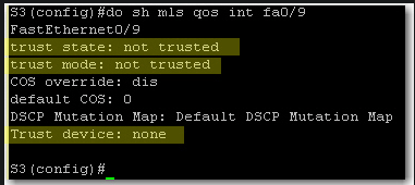
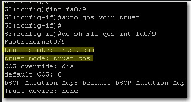
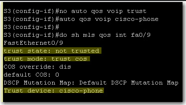
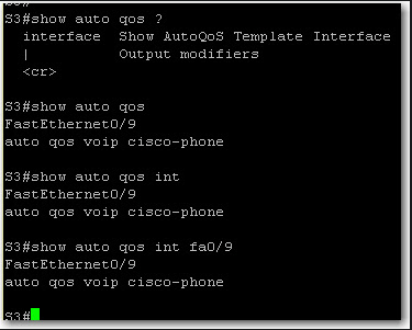
First, let’s see if QoS is enabled on the switch: autoqos01 QoS is disabled. We should enable it on global configuration level: autoqos02 If we want to display QoS settings for an interface, we do a show mls qos interface command: autoqos03 At this stage we still did not define trust boundaries. That’s why Trust State and Trust Mode say “not trusted”. And we did not specify whether we’ll trust a device or not. To define trust boundary with auto-qos, we either trust all CoS values coming on the switch interface or we trust CoS values only if an ip phone is connected to the switch port. With auto qos voip trust, we tell the switch to trust CoS on each packet coming on the switch interface: autoqos04 If we want to further limit trust boundary, we can tell the switch to trust CoS values only if a Cisco ip phone is detected on the port: autoqos05 Finally, on a 3550 switch, show auto qos and show auto qos interface give the same output: autoqos06

[Read]

Loop Guard on Cisco IOS

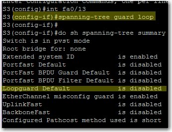
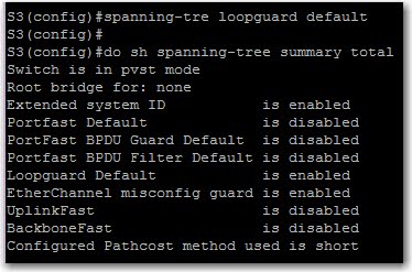
Enabling Loop Guard on an interface level does not enable it for the whole system. In fact, a “show spanning-tree summary total” is a bit misleading in this case.

To configure loop guard on an interface: sc1

“loop guard default” is disabled because we haven’t issued a “spanning-tree loopguard default”. Easy: sc2

[Read]

QoS Configuration and Verification on Cisco IOS

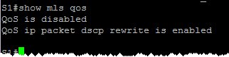
verify that QoS is enabled: sc1

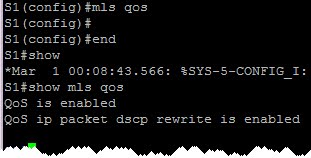
Enable QoS: sc2

At this stage, all interfaces are by default untrusted. This means that any frame with a priority value will be remarked as CoS/IP Precedence/DSCP value = 0.

Trust CoS values of incoming frames. Useful for trunks: sc3

Trust CoS values only if an attached Cisco ip phone exists (conditional trust): sc4

At this stage, the trust boundary moves to the IP phone. Any priority value of any attached PC frames is untrused, thus remarked with priority 0.

[Read]