Posts for: #Aci

ACI L4-7 Service Insertion: Service Graph Mgmt Modes

There are three ways to manage L4-7 services when we use service graphs. So if no service graph is inserted, we do not talk about these management modes!

[!Abstract] Unless otherwise specified, when Service Graphs are mentioned, then I am referring to the Unmanaged Mode.

Service Graph in Managed Mode (deprecated concept)

aka Service Policy mode: horizontal integration; requires a Device Package.

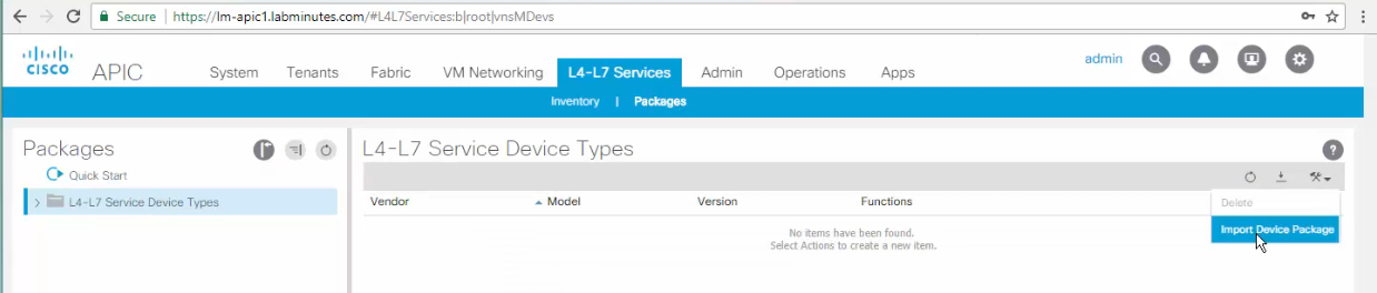
Device Package
sc1

adding a Device Package

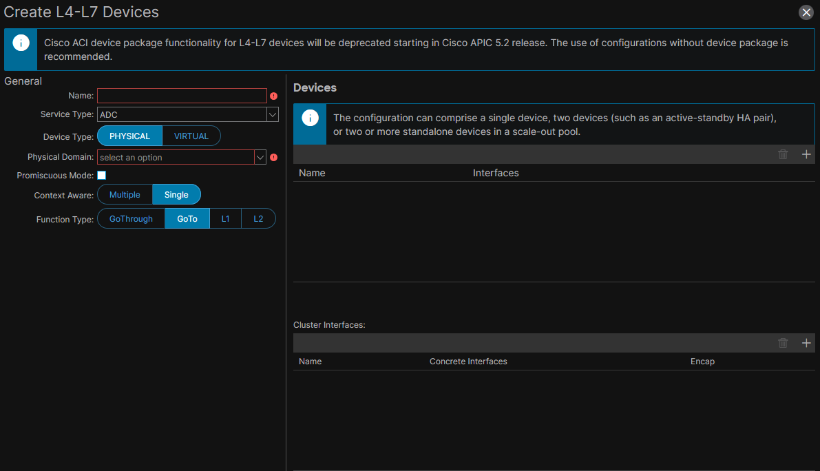
sc2

[Read]

ACI L4-7 Service Insertion: Service Graph with PBR

[!TLDR] Personal Observation I find few sources discussing standard SG and more literature discussing SGR. It seems to me that Cisco is pushing toward SG with PBR whenever a design involves L4-7 Service Devices.

aka Service Graph with Policy-Based Redirect, Service Graph Redirect. I call it SGR. One-Node SGR: Service Graph with one PBR Node.

Concept of a multi-node Service Graph

the concept of node in the terms ‘single-node SG’ or ‘multi-node SG’ refers to the L4-7 Devices in the SG. So, the term ‘multi-node Service Graph’ refers to a Service Graph with multiple L4-7 Devices, where each L4-7 Device could be:

[Read]

ACI Multi-Pod and Active-Standby Firewall in Routed Mode

Stretched Active/Standby Firewall

I must define an ACI L4-7 Device with two Concrete Devices; One for the Active node and one for the Standby node. See ACI Multi-Pod and Service Node Integration, page=5. The active firewall is in pod A, the standby firewall is in pod B. Support east-west and north-south traffic flows. No risk of asymmetric traffic flows because there is only one active firewall at a time.

Impact of traffic hair-pinning

Hair-pinning is a sub-optimal yet not avoidable traffic pattern. Beware of the latency impact of any hair-pinning traffic between pods due to traffic traversing the active firewall. The worst-case occurs when:

[Read]

Cisco ACI L4-7 Service Insertion: Standard Service Graphs with Firewall in Go-To Mode

#QA SSG with L4-7 Device in Go-To mode: in which situations do we need only layer-2 BDs attached to the Device? Layer-3 BDs? one Layer-2 and one Layer-3 BD? what is the recommended design? Go-To mode == Routed mode When NAT needed on the L4-7 Device: use Service Graph in Go-To mode with NAT. another ‘sub-mode’ is an L3Out between the L4-7 Device and ACI. With both NAT sub-mode and L3Out sub-mode:

[Read]

Inserting firewall packet inspection services in Cisco ACI data paths without offloading the gateway service off the fabric

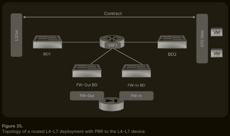
PBR in two-arm design, the PBR Node Interfaces are in the same VRF

sc1

#QA In the SGR in Go-To in Two-arm design, how does IP routing on the firewall scale when we have dozens of (Provider, Consumer) pairs? #QA How cumbersome is the management of the static IP routes related to the SGR on the service device? #QA Is BD2 the IP default gateway for EPG Web endpoints? #QA Which component takes the role of IP default gateway of the firewall: BD1 or FW-Out BD?

[Read]

ACI Bridge Domains

Bridge Domains and Subnets

A bridge domain can be configured with an IP subnet; it is then called a layer-3 bridge domain. The BD subnet is aka ACI internal subnet.

The IP address that we configure under the bridge domain is the IP default gateway of the IP subnet. The IP address is configured using a CIDR notation.

Subnets configured under bridge domains are added to the leaf’s routing table as static routes.

[Read]