Posts for: #Cisco

ACI L4-7 Service Insertion_Failover Traffic Management

Failover traffic is not managed by L4-7 Service Graphs

See the document ACI Service Graph Design Guide for ACI 5.2 and Later.pdf, page=50.

With the ‘out-of-band’ method

Use the dedicated firewall failover link ports and firewall stateful failover link ports, or designate some ports for that role; Failover traffic and stateful failover traffic are said to be managed ‘out-of-band’

With the ‘in-band’ method

i.e. use the physical network of the data traffic for failover and stateful failover traffic too. When the firewall is attached to ACI, the physical network path of firewall traffic is the ACI fabric.
[Read]

ACI Multi-Site and Active-Standby Firewall Clusters with Service Graph Redirect

Technology in Nexus Dashboard Orchestrator Equivalent on APIC
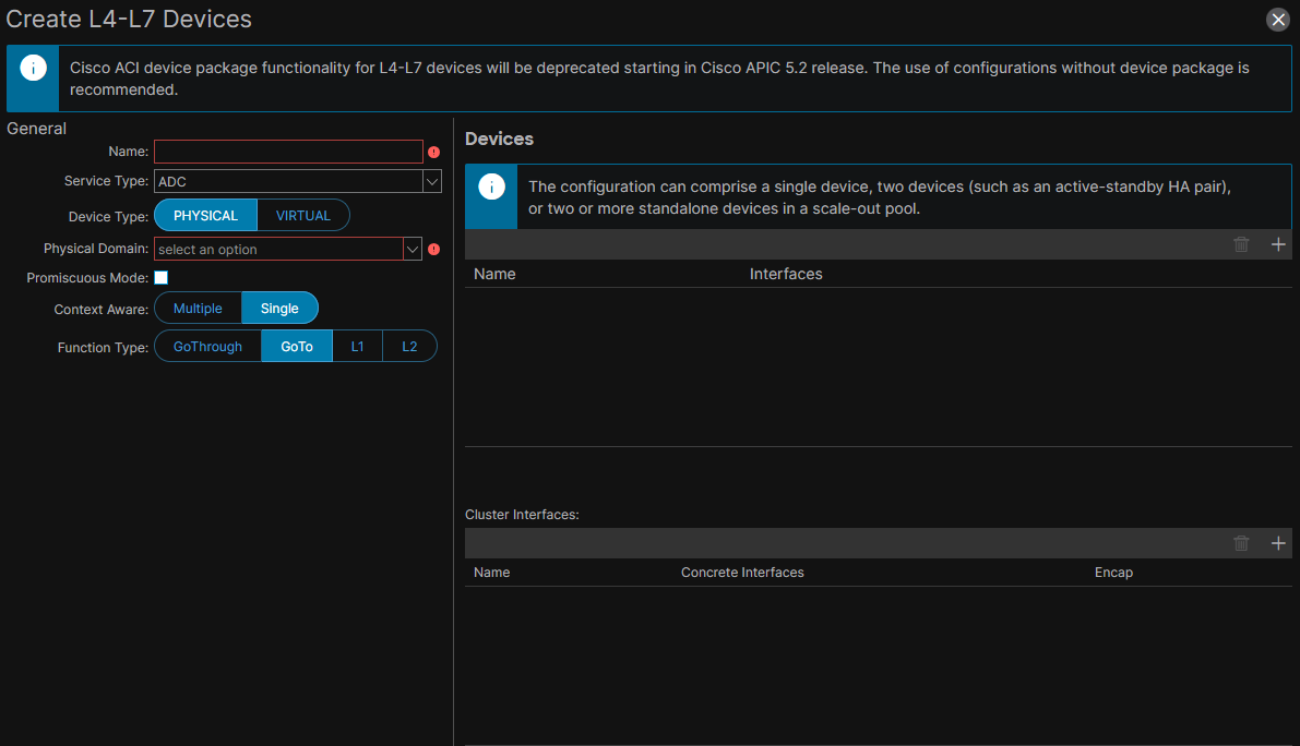
define a Service Service Device Cluster L4-7 Device, SGT

EPG-to-EPG PBR contract in ACI multi-site with independent HA-firewalls: I must define the BD subnet also under the consumer EPG and set the no Gateway SVI flag.

Contract Enforcement vs PBR Contract Enforcement vs PBR Policy Enforcement Contract enforcement == zoning rules are deployed to a leaf X. So leaf X takes action on the contract-matched traffic based on the deployed zoning rules. Leaf X is determined according to the Contract Policy Enforcement Locations table in the document ACI Contract Guide White Paper, page=20.

[Read]

ACI L4-7 Service Insertion: Service Graph Mgmt Modes

There are three ways to manage L4-7 services when we use service graphs. So if no service graph is inserted, we do not talk about these management modes!

[!Abstract] Unless otherwise specified, when Service Graphs are mentioned, then I am referring to the Unmanaged Mode.

Service Graph in Managed Mode (deprecated concept)

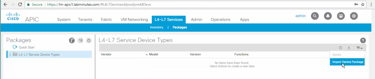
aka Service Policy mode: horizontal integration; requires a Device Package.

Device Package

sc1

adding a Device Package

sc2

[Read]

ACI L4-7 Service Insertion: Service Graph with PBR

[!TLDR] Personal Observation I find few sources discussing standard SG and more literature discussing SGR. It seems to me that Cisco is pushing toward SG with PBR whenever a design involves L4-7 Service Devices.

aka Service Graph with Policy-Based Redirect, Service Graph Redirect. I call it SGR. One-Node SGR: Service Graph with one PBR Node.

Concept of a multi-node Service Graph

the concept of node in the terms ‘single-node SG’ or ‘multi-node SG’ refers to the L4-7 Devices in the SG. So, the term ‘multi-node Service Graph’ refers to a Service Graph with multiple L4-7 Devices, where each L4-7 Device could be:

[Read]

ACI Multi-Pod and Active-Standby Firewall in Routed Mode

Stretched Active/Standby Firewall

I must define an ACI L4-7 Device with two Concrete Devices; One for the Active node and one for the Standby node. See ACI Multi-Pod and Service Node Integration, page=5. The active firewall is in pod A, the standby firewall is in pod B. Support east-west and north-south traffic flows. No risk of asymmetric traffic flows because there is only one active firewall at a time.

Impact of traffic hair-pinning

Hair-pinning is a sub-optimal yet not avoidable traffic pattern. Beware of the latency impact of any hair-pinning traffic between pods due to traffic traversing the active firewall. The worst-case occurs when:

[Read]

Cisco ACI L4-7 Service Insertion: Standard Service Graphs with Firewall in Go-To Mode

#QA SSG with L4-7 Device in Go-To mode: in which situations do we need only layer-2 BDs attached to the Device? Layer-3 BDs? one Layer-2 and one Layer-3 BD? what is the recommended design? Go-To mode == Routed mode When NAT needed on the L4-7 Device: use Service Graph in Go-To mode with NAT. another ‘sub-mode’ is an L3Out between the L4-7 Device and ACI. With both NAT sub-mode and L3Out sub-mode:

[Read]

Inserting firewall packet inspection services in Cisco ACI data paths without offloading the gateway service off the fabric

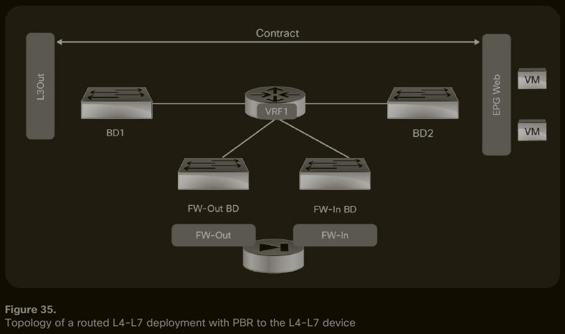
PBR in two-arm design, the PBR Node Interfaces are in the same VRF

sc1

#QA In the SGR in Go-To in Two-arm design, how does IP routing on the firewall scale when we have dozens of (Provider, Consumer) pairs? #QA How cumbersome is the management of the static IP routes related to the SGR on the service device? #QA Is BD2 the IP default gateway for EPG Web endpoints? #QA Which component takes the role of IP default gateway of the firewall: BD1 or FW-Out BD?

[Read]

ACI Bridge Domains

Bridge Domains and Subnets

A bridge domain can be configured with an IP subnet; it is then called a layer-3 bridge domain. The BD subnet is aka ACI internal subnet.

The IP address that we configure under the bridge domain is the IP default gateway of the IP subnet. The IP address is configured using a CIDR notation.

Subnets configured under bridge domains are added to the leaf’s routing table as static routes.

[Read]

How to Reload Your Cisco Router While Asleep

There are times when you want to schedule a router reload, but you don’t want to stay late or come to the office during weekends. “Reload at” is your friend.

How to reload your router at a predefined time

You want to reload your router (or switch) at 7pm, but at the same time, you’ll be having a coffee with your friend and you don’t want to have this discussion: “- Sorry guys, I have a router to reboot. I’ll be back in 30mn.

[Read]

Managing Endpoints and Endusers with CME

Preparing router to act as a CME:

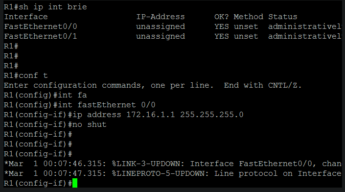
  • configure ip address on interface. sc1
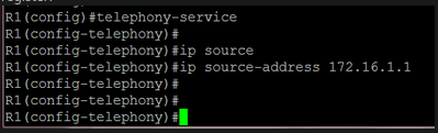
  • Configure the source address, the IP address to which ip phones will register: sc2
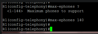
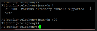
  • specify the maximum number of phones that CME can handle. This will affect the router performance: sc3
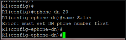
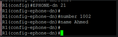
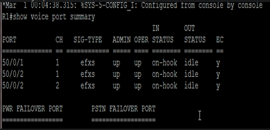
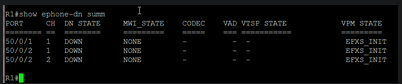
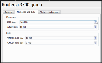
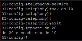
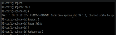
  • configure the maximum number of ephone-dns: sc4 Later, I will change these values because my router lacked memory resources. To verify the aforementioned settings: sc5 Let’s create our first ephone-dn: sc6 sc7 sc8 At this point, my router displayed an error message indicating a lack of memory. I increased its memory size in GNS3: sc9 After a reload, things went ok I also reduced the max-ephone and max-dn values: sc10 Now we can add ephone-dns without problems: sc11 When I create a dual-line ephone-dn, two “sub-ephone-dn” are created: sc12 To verify ephone-dns: sc13 another way to verify it: sc14 Notice that there are two channels for ephone-dn 2, which is a dual-line ephone-dn.
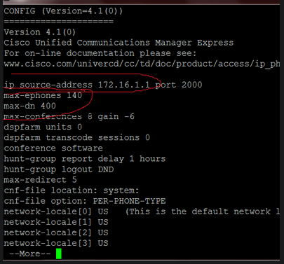
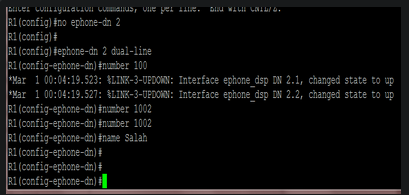
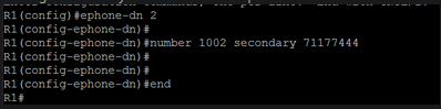
Adding a secondary line to a dual-line ephone-dn: sc15

[Read]